This document provides comprehensive study notes for the Amateur Station Operator’s Certificate (ASOC) Examination, covering both Restricted and General Grades. The content is synthesised from the official syllabus and study manuals, organised into Radio Theory (Section A), Radio Regulations (Section B), and Morse Code.
——————————————————————————–
Part I: Section A – Radio Theory and Practice
1. Elementary Electricity and Magnetism
Matter and Atomic Structure
- Matter: Exists in solid, liquid, or gaseous states and is composed of molecules and atoms.
- Atom: Consists of a positively charged nucleus (protons and neutrons) surrounded by negatively charged electrons in definite orbits.
- Valence Electrons: Electrons in the outermost orbit that determine the chemical properties and conductivity of an element.
- Conductors: Materials with partially filled outer shells where electrons can move freely (e.g., Silver, Copper, Aluminium).
- Insulators: Materials where the outer shell is completely filled, preventing electron flow (e.g., Glass, Ceramic, Plastic).
- Semiconductors: Materials like Silicon and Germanium that are neither good conductors nor good insulators.
Fundamental Electrical Units and Laws
- Current (I): The flow of free electric charge carriers (electrons, holes, or ions). Measured in Amperes (A).
- Electromotive Force (EMF): The force that causes the movement of electrons. Measured in Volts (V).
- Resistance (R): Opposition to current flow. Measured in Ohms (Ω).
- Conductance (G): The mathematical reciprocal of resistance (G = 1/R). Measured in mho.
- Ohm’s Law: The relationship where current is directly proportional to voltage and inversely proportional to resistance: I = V / R.
- Power (P): The rate at which work is done. P = V \times I or P = I^2 \times R. Measured in Watts (W).
- Energy: The capacity to perform work. Measured in Joules (J).
- Joule’s Law: Heat produced in a conductor is proportional to the square of the current, resistance, and time (H = I^2RT/J).
Passive Devices: Resistors, Capacitors, and Inductors
- Resistors: Components designed to provide specific resistance.
- Series: R_t = R_1 + R_2 + … + R_n (Current remains the same; voltage divides).
- Parallel: 1/R_t = 1/R_1 + 1/R_2 + … + 1/R_n (Voltage remains the same; current divides).
- Capacitors: Components that store electric charge using two conducting plates separated by a dielectric. Measured in Farads (F).
- Series: 1/C_t = 1/C_1 + 1/C_2 + … + 1/C_n (Total capacitance is less than the smallest individual value).
- Parallel: C_t = C_1 + C_2 + … + C_n (Equivalent to adding plate area).
- Inductors: Coils that oppose changes in alternating current. Measured in Henry (H).
- Self-Inductance: Ability to induce voltage in itself when current changes.
- Mutual Inductance: Ability of one coil to induce EMF in a nearby coil (the principle of transformers).
Magnetism
- Magnetic Flux: The group of magnetic field lines flowing from the North to South pole. Units: Maxwell (CGS) or Weber (MKS).
- Flux Density (B): Number of magnetic lines per unit area. Units: Gauss (CGS) or Tesla (MKS).
- Electromagnets: Coils with iron cores that act as magnets when current flows. Strength is adjusted via current magnitude and number of turns (Magneto-Motive Force, MMF = NI).
2. Alternating Current (AC) Fundamentals
- Sinusoidal Wave: A pattern of instantaneous changes in alternating voltage or current.
- Frequency (f): Number of cycles per second, measured in Hertz (Hz).
- Wavelength (\lambda): Distance travelled in one cycle. \lambda = c / f (where c is the speed of light).
- Values:
- Peak Value: Maximum value (V_M).
- Average Value: 0.637 \times \text{Peak}.
- RMS (Root Mean Square) Value: The equivalent DC value producing the same heating effect. V_{RMS} = 0.707 \times \text{Peak}.
- Reactance: Opposition to AC flow.
- Inductive (X_L): 2\pi fL.
- Capacitive (X_C): 1 / (2\pi fC).
- Impedance (Z): Total opposition in a circuit containing resistance and reactance. Z = \sqrt{R^2 + X^2}.
- Resonance: Occurs when X_L = X_C.
- Series Resonance: Minimum impedance, maximum current.
- Parallel Resonance: Maximum impedance, minimum current.
3. Transformers
- Purpose: To transfer electrical energy between circuits of the same frequency while changing voltage or current levels.
- Turns Ratio: N_s / N_p.
- Step-Up/Step-Down: If N_s > N_p, it is a step-up transformer; if N_s < N_p, it is step-down.
- Losses:
- Copper Losses: I^2R heat losses in windings.
- Hysteresis Losses: Due to friction in the core during magnetisation/demagnetisation.
- Eddy Current Losses: Circulating currents in the core; reduced by using laminated cores.
- Impedance Matching: Necessary for maximum power transfer; a transformer can match a low-impedance load to a high-impedance source.
4. Semiconductor Devices and Transistors
Diodes and Rectification
- P-N Junction: Formed by joining P-type (positive hole carriers) and N-type (negative electron carriers) materials.
- Biasing:
- Forward Bias: Positive to P, Negative to N; conducts current once the potential barrier (0.7V for Silicon, 0.3V for Germanium) is overcome.
- Reverse Bias: Prevents current flow; increases the depletion region.
- Rectifiers:
- Half-Wave: Conducts during positive half-cycles; 40.6% efficiency.
- Full-Wave: Uses two diodes and a centre-tapped transformer; 81.2% efficiency.
- Bridge Rectifier: Uses four diodes; eliminates the need for a centre-tapped transformer.
Transistors (BJT)
- Types: NPN and PNP.
- Terminals: Emitter (heavily doped, supplies carriers), Base (thin, lightly doped), and Collector (moderately doped, collects carriers).
- Configurations:
- Common Base (CB): High voltage gain, no current gain.
- Common Emitter (CE): High current and voltage gain; most widely used.
- Common Collector (CC): High input impedance, low output impedance; used for impedance matching (Emitter Follower).
5. Amplifiers and Oscillators
- Amplifier Classes:
- Class A: Conducts over the full 360° cycle; high fidelity, low efficiency.
- Class B: Conducts over 180°; high efficiency, used in Push-Pull arrangements.
- Class C: Conducts for less than 180°; high distortion, very high efficiency (85-90%); used for RF power.
- Oscillators: Sensitive amplifiers with positive feedback to sustain oscillations.
- L-C Tank Circuit: Energy oscillates between a capacitor and an inductor.
- Hartley Oscillator: Uses a tapped inductor for feedback.
- Colpitts Oscillator: Uses a tapped capacitance (two capacitors) for feedback.
- Crystal Oscillator: Uses the Piezoelectric Effect of quartz for high frequency stability.
6. Modulation and Communication Principles
- Modulation: Superimposing an Audio Frequency (AF) signal onto a Radio Frequency (RF) carrier wave.
- Amplitude Modulation (AM): Amplitude of the carrier varies with AF.
- Frequency Modulation (FM): Frequency of the carrier varies with AF; better noise immunity.
- Phase Modulation (PM): Phase of the carrier is shifted.
- SSB (Single Sideband): A form of AM where the carrier and one sideband are suppressed; highly efficient and saves bandwidth.
- Demodulation: The process of extracting the AF signal from the modulated carrier (detection).
7. Radio Receivers
- Characteristics:
- Sensitivity: Ability to pick up weak signals.
- Selectivity: Ability to separate desired signals from unwanted ones.
- Fidelity: Precision of reproduction.
- Superheterodyne Receiver:
- Converts incoming RF to a fixed Intermediate Frequency (IF)—typically 455 kHz.
- Stages: RF Amplifier → Mixer (combined with Local Oscillator) → IF Amplifier → Detector → AF Amplifier.
- Image Frequency: An undesired signal that can produce the same IF; mitigated by RF pre-selection.
- Squelch (Muting): Cuts off audio output in the absence of a carrier to eliminate noise.
- Automatic Gain Control (AGC): Equalises signal strength to prevent blasting or fading.
8. Radio Wave Propagation
- Electromagnetic Spectrum: Categorised from VLF (3–30 kHz) to EHF (30–300 GHz).
- Ground Waves: Follow the curvature of the earth; effective for low and medium frequencies.
- Sky Waves: Reflected by the Ionosphere for long-distance communication.
- Ionosphere Layers:
- D Layer: Lowest; disappears at night; absorbs HF.
- E Layer: Middle; reflects some HF during the day.
- F1 and F2 Layers: Most important for HF reflection. Combine into a single F layer at night.
- Skip Distance: The distance between the transmitter and where the sky wave first returns to earth.
- Skip Zone: The “dead” area where neither ground waves nor sky waves can be received.
9. Aerials (Antennas)
- Half-Wave Dipole: The fundamental antenna; length is approximately half the wavelength (\lambda/2).
- Centre impedance: ~72 Ohms.
- Standing waves: Voltage maximum at ends, current maximum at the centre.
- Yagi-Uda Antenna: A parasitic array with a driven element, a reflector (longer), and one or more directors (shorter). Provides high gain and directivity.
- Folded Dipole: A variation with higher input impedance (~288 Ohms), matching 300-ohm transmission lines.
- Polarisation: Determined by the orientation of the electric field (Vertical or Horizontal).
——————————————————————————–
Part II: Section B – Radio Regulations
1. Licensing and Eligibility
- Authority: Wireless Planning & Co-ordination (WPC) Wing of the Ministry of Communications, India.
- Eligibility: Indian citizens above 12 years of age.
- Grades: Restricted (No Morse test) and General (Includes Morse test).
- Exemptions: Degree/Diploma holders in Engineering/Science with electronics/telecom subjects are exempted from Section A (Radio Theory).
2. Operational Rules
- Permitted Messages: Plain language, technical nature, or personal remarks.
- Forbidden Messages: Business, politics, religion, advertisements, music, or third-party messages (except during disasters).
- Disaster Communication: Third-party messages are permitted during natural calamities (floods, earthquakes) if addressed to authorised officials like District Collectors.
- Secrecy: Operators must not disclose or use any misdirected correspondence received.
3. Frequencies and Emissions
- Frequency Units: VLF (3-30 kHz) to EHF (30-300 GHz).
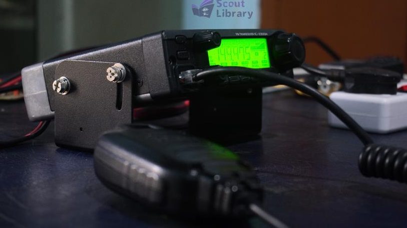
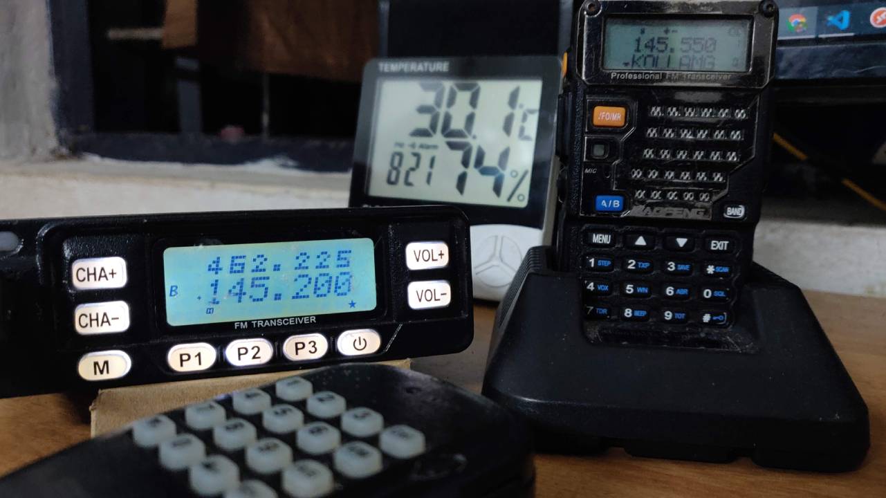
- Amateur Bands in India (Examples): 160M (1820-1825 kHz), 40M (7000-7200 kHz), 20M (14000-14350 kHz), 2M (144-146 MHz).
- Emission Designators:
- A1A: CW Morse Code.
- A3E: Double Sideband AM Voice.
- J3E: SSB Suppressed Carrier.
- F3E: Frequency Modulation Voice.
4. Station Management
- Logbook: Must be a bound book; entries must include date, time (IST), callsigns, frequency, mode, and power. Records must be preserved for one year.
- Callsigns: Assigned by WPC. Indian prefix is VU.
- VU2: General Grade.
- VU3: Restricted Grade.
- QSL Cards: Written confirmations of contact.
5. Priority Signals
- Distress: SOS (Morse) or MAYDAY (Voice). Used for grave/imminent danger.
- Urgency: XXX (Morse) or PAN PAN (Voice). Used for safety of a person or vehicle.
- Safety: TTT (Morse) or SECURITE (Voice). Used for weather warnings.
——————————————————————————–
Part III: Morse Code and Operational Aids
1. Morse Code (General Grade Requirement)
- Speed: 8 words per minute (wpm).
- Test: 5-minute reception and sending of a plain language passage (approx. 200 characters).
- Accuracy: Maximum 5 errors allowed.
2. Q-Codes (Morse & Voice)
- QRA: Name of station.
- QRG: Exact frequency.
- QRL: Frequency busy / I am busy.
- QRM: Interference from other stations.
- QRN: Interference from atmospherics (static).
- QRO/QRS: Increase power / Decrease speed.
- QRT: Stop transmission.
- QTH: Location.
- QSL: Acknowledge receipt.
- QRZ: Who is calling me?
3. Standard Phonetic Alphabet
- A: Alfa, B: Bravo, C: Charlie, D: Delta, E: Echo, F: Foxtrot, G: Golf, H: Hotel, I: India, J: Juliett, K: Kilo, L: Lima, M: Mike, N: November, O: Oscar, P: Papa, Q: Quebec, R: Romeo, S: Sierra, T: Tango, U: Uniform, V: Victor, W: Whiskey, X: X-ray, Y: Yankee, Z: Zulu.
4. Abbreviations
- CQ: General call to all stations.
- DE: “From” or “This is”.
- K: Go ahead.
- 73: Best regards.
- YL/OM: Young Lady / Old Man (Lady/Male operator).
- R: Roger (Received fully).
5. RST Reporting System
- Readability (1-5): 1 (Unreadable) to 5 (Perfectly readable).
- Signal Strength (1-9): 1 (Faint) to 9 (Extremely strong).
- Tone (1-9): 1 (Rough AC) to 9 (Perfect pure tone). Used only for Morse.